


Technical Parameter:
| Stroke Specifications | Unit | TV-80A |
| X/Y/Z axis travel | mm | 800/500/500 |
| Distance from spindle nose to work table | mm | 120-620 |
| Distance from spindle center to column | mm | 556 |
| Feed | ||
| Rapid feed (X/Y/Z axis) | m/min | 30/30/30(48/48/48) |
| Cutting feed | mm/min | 1 〜10000 |
| Feed motor power (X/Y/Z axis) | kw | 2/2/3 |
| Workbench | ||
| Table size (X/Y axis) | mm | 1000X500 |
| T-slot (width x number x spacing) | mm | 18X5X90 |
| Workbench maximum load | kg | 400 |
| Spindle | ||
| Spindle moving method | 一 | Direct connection/belt |
| Spindle Motor Specifications | kw | 7.5/11 |
| Spindle speed | rpm | 8000/10000/12000 |
| Spindle taper hole specification | - | BT-40 |
| Precision | ||
| Positioning accuracy(JIS B6228/6339) | mm | ±0.005 |
| Repeatability(JIS B6228/6339) | mm | ±0.003 |
| ATC | ||
| Tool magazine form | - | Knife arm |
| Tool magazine capacity | - | 24 |
| Maximum Tool Diameter/Air Knife | mm | Φ78/Φ120 |
| Maximum tool length | mm | 300 |
| Maximum tool weight | kg | 8 |
| Tool change time(T-T) | sec | 2 |
| Other | ||
| Electricity demand | kVA | 20 |
| Air pressure demand | kg/cm² | 6 |
| Cutting fluid capacity | L | 180 |
| Machine Weight (Approx.) | kg | 4600 |
| Appearance dimensions of the machine (length X width X height) | mm | Front row:2380*3780*2480(2800) |
| mm | Back row:2830*2480*2480(2800) | |
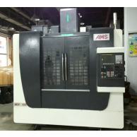
Overview
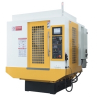
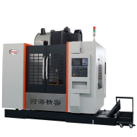
The vertical machining center is mainly used to process parts with high precision, many processes and complex shapes such as plates, discs, shells, molds, etc. It can continuously complete milling, drilling, expanding, boring and tapping in one clamping. And 2D and 3D curved surfaces, precise machining of inclined planes, and the realization of programming, shortening the production cycle, so that users can obtain good economic benefits.
1. Function and feature description
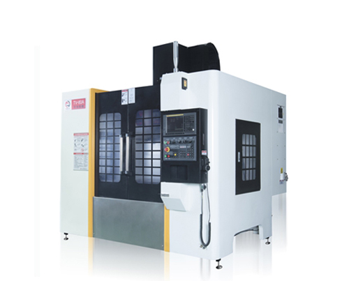
1 Overall layout of the machine tool
TV-80 vertical machining center adopts a vertical frame layout, the column is fixed on the machine body, the headstock moves up and down along the column (Z direction) / the sliding seat moves longitudinally along the bed (Y direction) / the worktable moves laterally along the sliding seat (X-direction) structure.
The bed, worktable, sliding seat, column, spindle box and other large parts are made of high-strength cast iron material, and the shape is resin sand process, and the stress is relieved by two aging treatments. These large parts are optimized by Pro/E and Ansys to improve the rigidity and stability of the large parts and the whole machine, and effectively suppress the deformation and vibration of the machine tool caused by cutting force.
The machine body adopts Meehan sodium cast iron structure and rigid box structure design, with high rigidity and high stability.
2 Drag system
X, Y, Z axes adopt Taiwan Shangyin/Intime or Germany Rexroth high-precision, heavy-duty linear guides, rolling instead of sliding, low friction loss, sensitive response, high positioning accuracy, X/Z axis using rollers / balls to lengthen The six-slide type design enhances the contact surface between the main shaft and the column casting, enhances the rigidity of the machine tool and the knob torque, fast cutting feed rate, low machining vibration, low speed without creeping, and improves the accuracy and stability of the machine tool. Higher surface quality of the workpiece can be obtained, and higher machining accuracy can be obtained due to good heat dissipation conditions and less thermal deformation of the workpiece.
Using Japan's P4 precision grade screw special bearings, symmetrical axial and radial preload ensure high-speed continuous operation afternoon noise.
The three-axis adopts Taiwan C3-grade precision ball screw with preload at the end, which ensures excellent transmission accuracy and positioning accuracy.
X, Y, Z three-axis servo motors are directly connected with high-precision ball screws through elastic coupling joints, reducing intermediate links, realizing gap-free transmission, flexible feeding, accurate positioning, and high transmission precision.
The Z-axis servo motor has an automatic brake function. In the event of a power failure, the brake can automatically hold the motor tightly, so that it cannot rotate, which plays a role in safety protection.
3 spindle groups
※The spindle group is produced by Taiwan professional manufacturers, with high precision and high rigidity. The bearing adopts P4 grade spindle special bearing. After the whole set of spindles is assembled under constant temperature conditions, they all pass the dynamic balance correction and running-in test, which improves the service life and reliability of the whole set of spindles.
※The spindle can realize stepless speed regulation within its speed range. The spindle is controlled by the built-in encoder of the motor, which can realize the function of spindle orientation and rigid tapping.
※The main shaft is made of nickel-chromium-molybdenum alloy steel, and after heat treatment, it has a tensile strength of up to 90Kg/mm2. The spindle is equipped with two front bearings and two rear bearings. It ensures the rotation accuracy and rigidity of the spindle under high-speed operation.
※Using German grade P4 precision bearings, the characteristics of slow temperature rise, small thermal deformation, high temperature resistance, and symmetrical axial and radial preload ensure noise-free operation under high-speed continuous operation.
4 Cutting cooling system
Equipped with a large-flow cooling pump and a large-capacity water tank to fully ensure circulating cooling, cooling pump power: 1.0Kw, flow: 60L/min.
The end face of the headstock is equipped with cooling nozzles, which can be either water-cooled or air-cooled, and can be switched at will. The cooling process can also be controlled by M code or control panel.
Equipped with a cleaning water gun to clean the machine.
5 Pneumatic system
The pneumatic triplet can filter impurities and moisture in the source, preventing impure gas from damaging and corroding machine tool components. The solenoid valve group is controlled by the PLC program to ensure that the spindle loosening, the spindle center blowing, the spindle clamping, and the spindle air cooling can be completed quickly and accurately.
Configure the cleaning air gun to clean the machine.
6 Machine tool protection
The machine tool adopts a fully enclosed protective room, which not only prevents the coolant from splashing, but also ensures safe operation and pleasant appearance. Each guide rail of the machine tool has a stainless steel telescopic protective cover to prevent cutting and coolant from entering the machine tool, causing the guide rail and ball screw to be worn and corroded.
7 Lubrication system
The guide rail and ball screw pair all adopt the central centralized thin oil automatic lubrication system. Each node is equipped with a volumetric oil separator, which regularly and quantitatively injects oil into each lubricating part to ensure uniform lubrication of each sliding surface, effectively reducing frictional resistance and improving The movement accuracy ensures the service life of the ball screw pair and the guide rail.
8 chip removal system
The iron filings generated during the machining process fall directly onto the guard room, and the protective internal inclined surface structure makes the iron filings fall into the chip flute smoothly, and then the iron filings are sent to the chip conveyor behind the machine tool by flushing water, which greatly reduces labor amount of labor.
9 Machine tool working conditions
(1) Power supply: 380V±10% 50HZ±1% three-phase alternating current
(2) Operating temperature: 5℃-40℃
(3) Best ambient temperature: 15℃-25℃
(4) Relative temperature: 40-75%
(5) Air source pressure: 0.5-0.7Mpa/6-8kgf/cm3
(6) Air source flow: 350L/min
10 CNC system
♢10.4 inch LCD display, Chinese and English display
♢Support standard RS232 and USB interface or CF card interface, network interface can realize data communication transmission
♢ Serial DNC processing and USB online processing functions
♢ For other performance parameters, please refer to the system manual
CNC system function introduction
♢The numerical control system is a high reliability and cost-effective numerical control system. It has a fully digital structure and powerful processing capability, and can control up to 4 coordinates and 1 serial spindle at the same time.
♢The numerical control system, together with the latest digital servo and integrated PMC, constitute a fully digital control system with excellent dynamic quality and control precision.
♦Hardware configuration
♢ Operation panel: full-function CNC keyboard
♢PMC: Built-in PMC SA1, 8000 steps.
♢ CNC user storage capacity: 512KB (equivalent to 1280m tape), 600 programs, used to store user programs and data.
♦CNC function
♢ Minimum input increment: 0.001mm, 0.001deg, 0.0001inch
♢ Compensation functions: backlash compensation, stored pitch error compensation, tool length and tool radius compensation
♢Feed function: rapid feed, feed per minute, inverse time feed, automatic acceleration and deceleration, AI advanced control
♢ Spindle function: spindle serial output, spindle speed function, spindle override adjustment, spindle orientation
♢ Coordinate system setting
♢ Scaling, coordinate system rotation, programmable mirroring
♢ Rigid tapping
♦ CNC programming
♢ Programming language: tape code (EIA RS244/ISO840) Metric/Imperial programming
♢ Absolute/incremental programming and mixed programming of absolute and incremental in the same block ● Polar coordinate instruction programming
♢ External storage 10 levels of nested subroutine calls
♢Drilling fixed machining cycle user macro program B ● Workpiece coordinate system (G52-G59)
♢ Select block to skip automatic corner override/deceleration ●Chamfer/Round transition plane selection
♦ Interpolation type
Positioning, one-way positioning, accurate stop, three-coordinate linkage, arbitrary two-coordinate circular interpolation, feed pause, helical interpolation (circular interpolation + linear interpolation of up to two axes), thread cutting, synchronous cutting, normal directional control.
♦ How to operate
AUTO operation, DNC operation, MDA operation, JOG feed, manual reference point return, handwheel interruption and recovery, incremental feed, dry run, single block mode, handwheel feed.
♦ Edit function
Program segment retrieval, program number retrieval, background editing, program protection.
♦ Display function
Current position display, actual cutting speed display, program display, clock display, running time and component technology display, alarm information display, self-diagnosis function display, NC and PLC signal status display, ladder diagram display.
♦ Safety protection function
Stored stroke limit monitoring, hardware limit monitoring, emergency stop, static monitoring, speed monitoring, position monitoring, contour monitoring. Safety functions also constantly monitor measurement circuits, overheating, voltage, memory.
♦ Data transfer
Through RS232 serial interface and USB interface or CF card interface can realize data input and output transmission.
11 tool magazine
♦ Disc magazine
The indexing mechanism adopts a combination of cylindrical cams, which has high indexing accuracy and low noise; the tool holder is light in weight and has good stability, and runs smoothly and without noise; the tool change time is short, and the operation has no impact; the tool magazine is controlled by proximity switches to ensure accurate movements. .